Fix thermal-pressure motor lock: Difference between revisions
Robertbaxter (talk | contribs) No edit summary |
Robertbaxter (talk | contribs) No edit summary |
||
| (9 intermediate revisions by 2 users not shown) | |||
| Line 3: | Line 3: | ||
|time=90 min. | |time=90 min. | ||
|type=Maintenance | |type=Maintenance | ||
|series=RZ series, EZ series, SF series, MZ series | |series=RZ series, RV series, EZ series, EV series, SE series, SF series, MZ series, MV series, ME series, MD series, MF series, MH series | ||
|tools | |tools=Phillips #2 screwdriver, Flathead screwdriver, Needlenose pliers | ||
|parts={{Tutorial/part | |parts={{Tutorial/part | ||
|part_number=612-10010 | |part_number=612-10010 | ||
| Line 24: | Line 18: | ||
}} | }} | ||
}} | }} | ||
This tutorial<ref>This tutorial is adapted from an original submission by [[RISOFORT| | This tutorial provides step-by-step instructions to replace a broken gear (part no. <code>612-10010</code> referred to colloquially as the "TPH gear") in the gear box for the ''thermal pressure motor''—it's used in all Z+ type machines.<ref>This tutorial is adapted from an original submission by [[RISOFORT|Risofort.]]</ref> | ||
== Overview == | == Overview == | ||
The gear in | The thermal pressure system is used to keep the TPH{{#info:Thermal Print Head|note}} pressing the stencil material against the write roller, to ensure a clean image is burned. A great deal of force is put on this gearing, and this gear in particular will snap and shatter as the system wears. When it does it will generate <code>T19</code> or <code>P19</code> errors and the riso will be unable to make a stencil and the whole machine will be locked in "call service mode." | ||
There is a known flaw in the manufacture of this gear, and the shaft system it sits on.<ref>PART CHANGE INFORMATION | |||
<br/>ISSUE DATE: 12/19/2008<br/>EZ2/3/5, RZ9 AND MZ SERIES TPH PRESSURE MOTOR ASSY<br/>Document No: 22679</ref> While adjustments were made to the design of this area on some models, broken gears are still being found across multiple machines. | |||
The part can be replaced, but it takes a little while to get enough access to remove it and swap the new one in—this is process is also slowed by the caution required when working with the TPH. | |||
''It's recommended that anyone running an RZ or newer machine have 1–2 replacement gears on hand.'' They are readily available on eBay and AliExpress by searching by the part number <code>612-10010</code>. | |||
== Replacement procedure == | |||
The process of replacing this part is a little different between one- and two-drum machines (and depending on the make of your machine you may need to remove some additional covers to get access to things). It will take about 90 minutes the first time you do it (but can be done much more quickly once you know your way around). | |||
=== Getting into the risograph === | |||
First, to access the sections we need, we'll need to pull the MMU (master making unit) out of the machine. Follow the steps you'd take to replace the stencil roll on your machine to get the MMU out (pushing the green button either to the right of the drum removal button on one-drum machines, or on the right side of the riso on two-drum machines). | |||
<u>Before you go any further, '''turn off and unplug the riso'''. From here on you'll exclusively be working on it ''unpowered''—until the replacement is finished and everything is reassembled.</u> | |||
=== Accessing the pressure assembly === | |||
In order to replace the gear, we'll need to get into the TPH ''pressure assembly'', the gearing inside the panel with the TPH that you lift up and click down when replacing the stencil roll. The method for getting into this area is different for one and two drum machines. | |||
==== Accessing the gearbox cover on one-drum machines ==== | |||
{{mbox|title=One-drum instructions|text=The steps in this section are for ''machines with <u>one drum</u> only''.|color_bar=#BB76CF|icon=record-vinyl}} | |||
==== Accessing the gearbox cover on two-drum machines ==== | |||
{{mbox|title=Two-drum instructions|text=The steps in this section are for ''machines with <u>two drums</u> only''.|color_bar=#BB76CF|icon=voicemail}} | |||
==== Removing the TPH (thermal print head) ==== | |||
==== Removing the TPH support bar ==== | |||
==== Removing the TPH gearbox ==== | |||
=== Replacing the TPH gear === | |||
=== Notes on reassembly === | |||
== (Old instructions) == | |||
=== Configure === | === Configure === | ||
==== 1: Remove the outer cover of the Master Removal Unit (feed side) ==== | ==== 1: Remove the outer cover of the Master Removal Unit (feed side) ==== | ||
Latest revision as of 18:39, 9 June 2025
| Fix thermal-pressure motor lock | |
|---|---|
| Difficulty | Intermediate |
| Duration | 90 min. |
| For series | RZ, RV, EZ, EV, SE, SF, MZ, MV, ME, MD, MF, MH |
| Tools | Phillips #2 screwdriver Flathead screwdriver Needlenose pliers |
| Parts | 612-10010 1 × TPH Gear |
| Error codes | T19-XXX Thermal pressure motor lock !!System Error!!</br>Press Reset Key</br>If Recovery has Failed, Call Service |
This tutorial provides step-by-step instructions to replace a broken gear (part no. 612-10010 referred to colloquially as the "TPH gear") in the gear box for the thermal pressure motor—it's used in all Z+ type machines.[1]
Overview
The thermal pressure system is used to keep the TPHThermal Print Head pressing the stencil material against the write roller, to ensure a clean image is burned. A great deal of force is put on this gearing, and this gear in particular will snap and shatter as the system wears. When it does it will generate T19 or P19 errors and the riso will be unable to make a stencil and the whole machine will be locked in "call service mode."
There is a known flaw in the manufacture of this gear, and the shaft system it sits on.[2] While adjustments were made to the design of this area on some models, broken gears are still being found across multiple machines.
The part can be replaced, but it takes a little while to get enough access to remove it and swap the new one in—this is process is also slowed by the caution required when working with the TPH.
It's recommended that anyone running an RZ or newer machine have 1–2 replacement gears on hand. They are readily available on eBay and AliExpress by searching by the part number 612-10010.
Replacement procedure
The process of replacing this part is a little different between one- and two-drum machines (and depending on the make of your machine you may need to remove some additional covers to get access to things). It will take about 90 minutes the first time you do it (but can be done much more quickly once you know your way around).
Getting into the risograph
First, to access the sections we need, we'll need to pull the MMU (master making unit) out of the machine. Follow the steps you'd take to replace the stencil roll on your machine to get the MMU out (pushing the green button either to the right of the drum removal button on one-drum machines, or on the right side of the riso on two-drum machines).
Before you go any further, turn off and unplug the riso. From here on you'll exclusively be working on it unpowered—until the replacement is finished and everything is reassembled.
Accessing the pressure assembly
In order to replace the gear, we'll need to get into the TPH pressure assembly, the gearing inside the panel with the TPH that you lift up and click down when replacing the stencil roll. The method for getting into this area is different for one and two drum machines.
Accessing the gearbox cover on one-drum machines
Accessing the gearbox cover on two-drum machines
Removing the TPH (thermal print head)
Removing the TPH support bar
Removing the TPH gearbox
Replacing the TPH gear
Notes on reassembly
(Old instructions)
Configure
1: Remove the outer cover of the Master Removal Unit (feed side)

- Unscrew and remove the outer cover (5 screws in total). The left side may be slightly hooked.
2: Remove the top cover of the paper feed

- Unscrew and remove the plastic cover (2 screws). Pull the cover towards you and set it aside.
3: Disconnect cables and remove the Master Removal Unit

- Unplug 2 cables and the connector. Remove the cable clamp.
- Unscrew 2 screws holding the Master Removal Unit in place.
- Carefully pull the unit out; it is heavy.
4: Push the MMU towards the paper feed side

- Open the cover of the Master Making Unit (MMU) and push the MMU towards the opposite side. If it doesn’t move, proceed to the next step.
5: Press the plastic hook to advance the MMU

- Push the hook to allow the MMU to slide further into the machine.
6: Push the MMU all the way in

- Continue pushing the MMU until it stops.
7: Remove screws from the Thermal Pressure Gear Cover

- From the paper feed side, unscrew 2 screws. Hold the MMU to prevent it from sliding back.
Open and disassemble the MMU
8: Remove the MMU bottom cover
- Unscrew 2 screws and set the cover aside.
9: Remove the TPH

- Avoid touching the TPH stripe (yellow/orange color).
10: Lift and remove the top bronze bearing metal.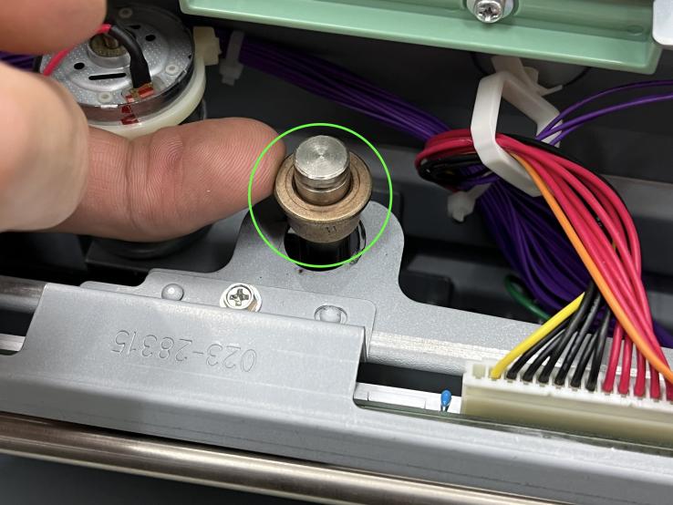

- Remove the black plastic snap ring and spring, and carefully remove the bronze bearing
11: Unplug 2 cables connected to the TPH

12: Carefully lift the TPH while holding the lower bronze bearing metal

- Before you can fully remove the TPH, you need to unscrew the grounding wire (see next step).
13: Unscrew the grounding wire

- Hold the TPH and unscrew the grounding screw (green, used with an eyelet to safely direct electricity to the ground) , ensuring it does not fall inside the MMU.
14: Set the TPH aside for now

- !!! Be careful to not touch the orange strip !!!
15: Remove the top screws of the Thermal Pressure Gear Cover

- Unscrew the top 2 screws to remove the cover.
Inspect and replace the gear
16: Check the gear

- Inspect the gear for damage. If it is intact, the issue may be elsewhere. It should be fairly obvious that the gear is broken, as you will likely find broken parts at the bottom of the enclosure.
- If the gear is not broken, you likely have a different issue.
17: Remove springs from the fulcrum shaft

- The fulcrum shaft is the black horizontal shaft. It needs to be removed to access the broken gear.
- Remove the springs with care, as they are under tension.
18: Remove e-rings from both sides of the fulcrum shaft

- Be careful: e-rings are tight and can jump off. Use special e-ring pliers or a screwdriver.
19: Remove the fulcrum shaft

- Extract the shaft to access the gear.
- Unscrew the white plastic piece and any remaining gear fragments. - Remove the tiny e-ring and push the shaft to the left.
21: Install the new gear
- Slide the new gear onto the shaft. - Reassemble the shaft and ensure the white plastic piece faces inward.
Put it back together
18: Reassemble =
- Grease the new gear and reassemble all components in reverse order.